 Global Service Hotline +86-18729329559


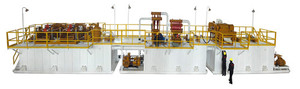
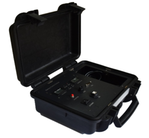


Surface well testing unit
Product Parameters
Product Parameters
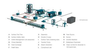
Surface well testing unit 1.Surface Safety Valve with ESD system1Pressure rating: 5,000-psi WPTemperature rating upto 250°F3” Nom. ID,Hydraulic Fail Safe to close Gate ValveIndependent unit with supporting base and frame mounted with certified lifting eyes and slingsApplicable design codes: API-6A ( PSL-2), NACE MR 0175Hydraulic operated ESD system shall be capable of shutting in the well on SSV.Activation shall take place as automatic functions from sensors installed as mutually agreed using API 14C as a guideline, or by manual activation of ESD buttons(pull to close) located at specified places (minimum 3 positions excluding the button on control panel)Remote operated - at least from 50m distance.Operates on air supply 50 to 100 psiPneumatic hoses and Button boxesIndicator signs(properly secured) in English and Hindi (all weather proof)Shut down time shall be less than 10 sec.2Data Header2One each for upstream and downstream of the choke manifold3” Nom. IDPressure rating: 5,000-psi WP (upstream) and 2500psi (downstream)Temperature Rating upto 250°FPorts(minimum 6 in no.) to allow temperature and pressure monitoring, chemical injection, sampling and to permit the hook up of Hi-Lo pilotsAll ports to be fitted with 2ea of 5,000 psi WP needle valves.Applicable design codes: ANSI B31.3,NACE MR 01753Choke Manifold13” hammer unions on inlet and outletAPI 6A PSL-2 (DD NL) gate valvesFixed choke bean as follows:-1 x full set of choke beans (and spares) Tungsten carbide fixed beans from: 8/64" to 32/64" (in 2/64" increments), 32/64" to 64/64" (in 4/64" increments) and 64/64" to 128/64" (in 8/64" increments)-1 x set of choke beans (and spares) upto 32/64"1 x adjustable chokes:Tungsten carbide adjustable choke range upto 128/64"3-1/8” 5k valves (and spares)Pressure rating: 5,000-psi WPTemperature Rating upto 250°FMinimized footprint.Tungsten carbide adjustable choke range from fully closed to 128/64"Applicable design Codes: ASME VIII div 1, ANSI B31.3, PSL-2, NACE MR 01754Oil Manifold13” Nom. ID1,440 psi Working Pressure.Min acceptable working temp is 212°F1ea of Five way manifold with 602 end connectionsApplicable design Codes: ASME VIII div 1, ANSI B31.3, NACE MR 01755Gas Manifold13” Nom. ID1,440 psi Working Pressure.Min acceptable working temp is 212°F2 ea of Three way manifold with 602 end connectionsApplicable design Codes: ASME VIII div 1, ANSI B31.3, PSL-3, NACE MR 01756Data Acquisition System1Trailer/Skid MountedElectronic Sensors for gathering flowing real time data.Pressure sensors for recording and displaying:Annulus Pressure,Upstream Choke pressure ( Well head pressure)Downstream choke pressureSeparator PressureSeparator gas differential pressure.Temperature sensors for recording and displaying:Annulus Pressure,Upstream Choke temp ( Well head temp)Downstream choke tempSeparator temp (gas and liquid each)Separator oil line tempSensors for gathering data for gas and liquid flow rates must collect data from exactly the same points as data used to compute flow rates by conventional methods.Sensors for recording and displaying separator liquid flow volume. Means of computing and printing:Separator gas flow rateSeparator liquid flow rateSeparator gas liquid ratiosCumulative gas productionCumulative liquid productionCapability of producing real time plots of Pressure vs. Time and of Flow rate vs. Time.Capability of producing daily data summary: Date & Time, choke size, THT,THP, Ann. P., Sep. Press., Sep. Temp., Oil SG, Gas SG, BSW, Oil rate, Oil Cum., Oil Shr., Gas rate, Gas Cum., water rate, GOR, CGR,WGR.DPR should be produced in a standard legitimate format.Suitable electronic data acquisition system, equipped with a laptop and required software for Well Test to handle large amount of data and uninturrupted monitoring.Soft copy ( electronic form ) of the data should be produced as per requirement.Acquisition system should be Zone II compatibleMinimum data gathering rate of 1 second per setTenderer to detail flow rate calculation methods in tender response.73 Phase Horizontal Separator I1Min. 1440 psi working pressure with Sizing suitable to handle the well parameter.Equipped with level controlled-SSV shut off automated system which automatically shuts off SSV incase the high-high level is achieved.3” /4" hammer union on inlet3” /4" hammer union on gas outlet3” /4" hammer unions on oil and water outletsGas meter run(s) with orifice meter(s) to measure from 0.1 to 10 MMscfdOil meter run(s) with flow meter(s) to measure from 50 to 5000 bopd. Contractor to mention the details of the flow meter and the maximum reliable flow rate which it could measure.Separator to be able to measure the specified maximum gas and liquid rates simultaneously.Inbuilt Oil shrinkage testerWater meter run with flow meter to measure from 50 to 3000 bwpd. Contractor to mention the dimension of the water line on which the meter would be installed.Contractor to mention the details of the flow meter and the maximum flow rate which it could measure.Three pen pressure recorder: Static pressure – 0 to 1500 psiDifferential pressure – 0 to 400 inches of waterTemperature – 0 to 60 deg CGas metering to measure from 0.1 MMSCFD to miniumum 10 MMSCFD. Contractor to mention the lowest and highlest flow rate possible to be measured with the proposed meter. The orifice plates of proposed sizes should come with complete back up plates. Contractor to mention the line sizes on which the meters would be installed.Balanced safety relief valvePilot operated PSVBypass manifold on oil and gas lineRacks with set 3” and 2” 602 hammer union pipingApplicable design Codes: ASME VIII div 1, ANSI B31.3, API RP 520/521, NACE MR 01752ea of Independantly mounted PSV.8Surge Tank1Alarm at the high-low level of the surge tank.Equipped with level controlled-SSV shut off automated system which automatically shuts off SSV incase the high-high level is achieved.100 bbl dual compartmentPressure rating: 150 psiSurge tank to be rated to a working temp of 212 °FSuitably sized and rated PSVGraduated Water / Oil interface sight glassOil resistant transparent coat inside sight glassGrounding deviceDrain valve and piping to allow flow of water to water treatment package or slops tank.Flame arrestor is required in gas Vent line.Applicable design Codes: ASME VIII div 1, ANSI B31.3, PSL-3, NACE MR 01759Oil Transfer Pump1Minimum 5000 BPD at minimum 100 - 150 psi dischargeIntrinsically safe explosion proof motor with sufficient electrical cabling to permit hook-upZone II 3 phase, 440 V, 50/60 HzDGMS certified Starter, junction box and accessories.Applicable design codes: NACE MR 0175, ASME B16.5.The oil transfer pump with motor should be skid mounted with dedicated slings10Chemical Injection Pump1Pumping capacity of minimum 20 GPD at 5,000 psi for each pump unitFor use to inject chemicals, methanol/ glycol, PPD, de-emulsifier, having redundancy and equipped with filtration device (and associated certification).Pumps should be of suitable trim for the required service and chemicals such as Methanol11Laboratory and Testing equipment1Placed at a safe location. Intrinsically safe barrier to allow use of standard electrics insideTemperature controlledEmergency escape windor/hatch/doorEquipments to be supplied:Calibrated Dead weight tester with comprehensive range of weightsPortable gas gravity balance - Ranarex or equivalentFull range of hydrometersHand centrifuge - 100ml TubesChlorides/ refractometerDigital manometerRange of calibrated pressure gaugesFoxboro (or equal) surface pressure/temperature 2 pen chart recorder (0-5,000 psi and 0-250°F)Electronic pH Meter,Calibrated thermometerOnsite Analysis of CO2, H2S and as a minimum pH, Salinity and SG.12Oil Storage tank (200bbl)2Min. 200 bbls Oil Storage Tank (excluding dead volume) - Skid mounted, insulated with dedicated slings3" 602 hammer unions on inlet3" 602 hammer unions on oil outletExternally mounted sight glassEquipped with heating coil, calibrated dipsticks, flame arrestor.Applicable design Codes: ANSI B31.313Heating Units1Indirect Bath heater of capacity 2 - 2.5 MMBtu/hr.API 6A PSL-2 design, DD Fluid class, with automatic diesel shut down valve activated by pilot stoppage, flame and spark arrestor on burner air inlet and should be capable of heating well fluid upto 70 deg C.Pressure Rating: 5000 psi.Bypass manifold with 3-1/8” 5K Gate ValveTransfer Pump (one centrifugal pump of capacity > 100 bbl per/hour coupled suitable for Viscous Oil) with DGMS approved explosion proof electric motor & Cable.1 certified operator with minimum 2 years experience as Operator.14Vertical Flare Stack skid1Vertical Flare stack skid4" ( 6'' ) ID , Minimum 30 Ft heightApplicable codes & standards: SA 106 Gr.B, A 105, ASTM A36, NACE MR 0175Shall be equipped with auto and pilot ignition system and propane bottles with rackShall be equipped with Guy ropes & cement blocks of suitable weight for stabilityShould have Winch arrangementDedicated slingsRequired piping for flare line and relief lines connection will be provided by the contractor. Approximately 400 m will be required for connection. The required relevant cross overs, logistics and R/U must be provided by the Contractor .15KOD1Alarm at the high-low level of the surge tank.Equipped with level controlled-SSV shut off automated system which automatically shuts off SSV incase the high-high level is achieved.50 bbl capacityPressure rating: 150 psiKOD to be rated to a working temp of 212 °FSuitably sized and rated PSV.Graduated Water / Oil interface sight glassOil resistant transparent coat inside sight glassGrounding deviceDrain valve and piping to allow flow of water to water treatment package or slops tank.Flame arrestor is required in gas Vent line.3" Relief LineApplicable design Codes: ASME VIII div 1, ANSI B31.3, PSL-3, NACE MR 017516Horizontal Flare with auto-ignition system1Horizontal Flare SystemHorizontal flare tip with 3" /4" connectionShall be equipped with a pilot ignition system and propane bottles with rack . Required piping for flare line and relief lines connection will be provided by the contractor. Approximately 400 m will be required for connection. The required relevant cross overs, logistics and R/U must be provided by the Contractor . 17Sand Detection System1Temperature up to max 250 deg FClampon type sand detection system. ontractor to mention the detectable sand rate/conc. PossibleSoftware, computer system & accessories as required18Diesel Transfer Pump1Capable to transfer diesel at sufficient rate to drive all diesel driven equipment on a continuous basisIntrinsically safe explosion proof motor with sufficient electrical cabling to permit hook-up19LGMS1Temperature up to max 250 deg FConforms to all industry standards related to vessel, piping, valves, and serviceSafety features to be detailed in the bid technical documentAbility to measure 0.001 - 0.2 MMSCFD20Dual Pod Sand Filter1Pressure rating: 5,000 psi rated & to be sited upstream of well test choke manifoldTemperature rating (- 20 to 250°F)Supporting Pumps for flushing purpose. High Pressure pump is required for flushing. Contractor to provide the specification of high pressure & flow rate pump. The high pressure washer is also required to clean the filter. Discharge pressure ~ 1000 psi. Discharge Pressure not to exceed 80% DP across screens.Capacity to handle gas up to 10 MMscfd & liquid up to 8000 BLPDAdequate number of filters sized at 200 & 300 microns for the contract duration.Screens to be designed to handle a differential pressure of 1500 psiDual pod filter mechanism c/w interconnecting piping, bypass and drain valve.Inlet/ outlet 3” 1502 hammer unions, drain outlet 3” 1502Will have to operate while proppant/sand flowback from the well. Appropriate bleed off mechanism for both the pods is required.Adequate filter cleaning arrangement like karcher pressure pumpEasily replaceable pods with air winchApplicable design Codes: ASME VIII div 1, ANSI B31.3, NACE MR 0175, API 6A(PSL-3) PR 221Sand Trap - Sand Catcher1Pressure rating: 5,000 psi rated & to be sited upstream of well test choke manifold for sand cleanout jobsWorking Temperature: Till 121 deg CGas Flow Capacity upto 10 MMSCFDLiquid flow Capacity upto 8000 blpdInlet and Outlet Connection: Union or FlangeUnions: Fig 602, Fig 1002, Fig 1502Flanges: API 6A FlangesDesign Codes: API SPEC.6ASURFACE SAMPLING Package1Surface Sampling Package1 SetOil and Gas Package - Mercury freeCalibrated pressure gaugesCalibrated “Test” gaugeCertified Sample linesRange of certified fittingsSampling manifoldThermometersMeasuring cylindersFlexible linersVacuum pump2Gas Cylinders20 litre capacity2ea of 20 liter capacity cylinders of 1500psi working pressure to be provided. 2 ea of Gas bombs of 500-1000 cc of 1500 psi.1500 psi WP3Oil Cylinders600-700 cc capacity4 cylinders with 1500 psig WP to be provided1500 psi WP4Dead oil sample cans20 nos. of 1L, 5 nos. of 5L and 2 nos. of 10 L capacity IATA cans to be provided per unit5Water sample bottles1 litre plastic bottles as per requirement6Onsite AnalysisCO2 & H2S contentFull Onsite Water Analysis;As a minimum pH, Acidity/Alkalinity, SG |


